Hardware Installation
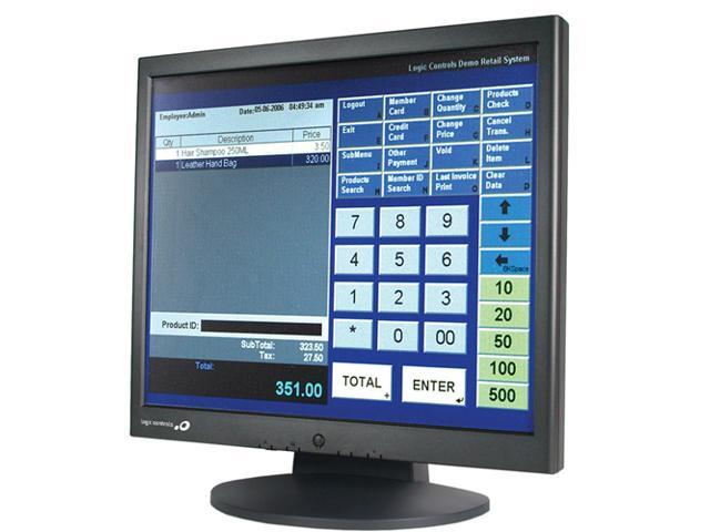
Be careful with your new LCD monitor, the monitor is very sophisticated and delicate. Turn off the monitor and the PC before you set it up. Follow the installation step by step.
Constructed with Logic Control's state-of-the-art PC Board and stainless steel dome disks, the KB1700 Programmable Keypad can even be customized and configured to support more than 17 keys. No programming kit, battery, or TSR program is required, and the keypad operates with or without a computer keyboard being attached. Logic Controls hardware is engineered and known worldwide to be very reliable in humid, harsh environments. Used in over 500,000 stations worldwide; quality and pride in engineering is our top priority – and it shows. More Information: Logic Controls LV3000 Part Number: This is a listing for individual item LV3000U. LV3000 LV3000U Logic Controls Logic Controls. Part Specifications: Color: Black. Display: 6.05 in. Resolution: 800 x 480. The LV3000U is one of this product's most popular models. Click HERE for all versions of the Logic Controls LV3000. USB Monitor software can be used on PCs, from Netbooks, Notebooks/Laptops to Desktops. The driver will run on processors ranging from Atom N270 based PCs, basic single Core CPUs, and the latest Dual, Quad Core and Core i3/i5/i7 CPUs.
Screw Specification for VESA Plate Stand or Wall Mount
Calibration Guide for Touch Panel

Linearization
1. Linearization ( 25 or 9 points calibration ) function is used to compensate the touch screen linearity. After linearization completed, the linearity of the touch screen will be shown in the Linearity curve window.
2. By pressing this button, a new window will pop up at the location to where the touch screen was mapped and guide the user to proceed the 25 points calibration. User should follows the guide to touch and hold the blinking X symbol in the calibration window until it does not blink and make sure the utility can gather enough data for computation. In addition, a time line bar would be shown at the bottom of the window to indicate time elapsed. If the touch screen was not touched before the time line bar goes to the right end, the calibration task will be terminated automatically.
Draw Test
This function is used for accuracy and performance check. By pressing this button, a new window will pop up at the location to where the touch screen was mapped. Screen as shown below.

User can press the Clear button to clear the window. Press Quit button to terminate this draw test. In drawing test window, users can verify the panel linearity, calibration capability, and drawing line quality.

Mouse Emulator
For more information please visit:http://bematechus.com/wp-content/uploads/2016/01/LE1017_UM.pdf
Drivers and Utilities
Logiccontrols Laptops & Desktops Driver Download
HARDWARE INSTALLATION

Logic Controls Laptops & Desktops Driver Downloads
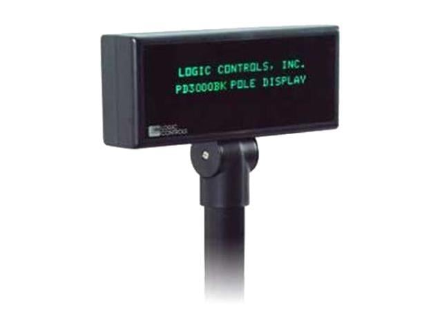
- Mount the pole display to the metal base plate using the mounting hardware provided.
- The pole display can be used in a freestanding mode or attached to the counter using the remaining mounting hardware.
- Install USB driver first as described in “DRIVER INSTALLTION” section.
- Plug the USB cable from the pole display into the computer’s USB port.
DRIVER INSTALLATION
The Windows XP/Vista USB drivers are available on our web site at www.bematechus.com. Please download and unzip the driver files before installation. There are two types of driver interface available. If the POS software is only able to access COM ports for the pole display, use the Virtual COM port interface. After the driver is installed, the USB interface will be assigned a COM port name so that the POS software will be able to communicate with the USB display as a COM port. Note that the operating system will assign the display a different COM port number if the display is plugged into a different USB port. Another driver interface use a specific device name (.LCLD1) to access the pole display directly. Install this driver if you are using OPOS or the POS software was tailored to use this device name.
- DO NOT plug the device in USB port.
- Run “install.bat” batch program in this driver package.
- Plug the device in USB port and wait for the hardware wizard message box to display.
- Click <Next> button to continue installation automatically. When finished, click <Finish> button to end installation.
- Invoke Device Manager to check COM port number or the device driver's name. The driver is installed under 'Ports (COM & LPT)'
- To change the assigned COM port number, double click 'LCI Line Display (.LCLD1) (COMx)' to display the Properties dialog box and select <Port Settings> tab. Then click <Advanced...> button.
- Click on COM port number box to select from the list of unused port number and click <OK> to accept new settings
- Unplug the display from the USB port for a few seconds and then plug the device back into the USB port. Device Manager should show the changed port number. Check operation with the new COM port number.
FOR MORE INFORMATION
For more information on the complete user manual, go to: Line Display User Manual
